Dell Dimension 9150/XPS 400 User Manual
Browse online or download User Manual for Computers Dell Dimension 9150/XPS 400. Dell Dimension 9150/XPS 400 User Manual
- Page / 148
- Table of contents
- TROUBLESHOOTING
- BOOKMARKS
- Owner’s Manual 1
- Notes, Notices, and Cautions 2
- Contents 3
- 4 Contents 4
- 6 Contents 6
- 8 Contents 8
- Finding Information 9
- 10 Finding Information 10
- 12 Finding Information 12
- Setting Up a Printer 13
- Connecting to the Internet 14
- Playing CDs and DVDs 16
- Adjusting the Volume 17
- Copying CDs and DVDs 18
- Using Blank CDs and DVDs 19
- Helpful Tips 20
- Connecting Two Monitors 21
- VGA (blue) connector 22
- DVI (white) connector 22
- TV-OUT connector 22
- Connecting a TV 23
- Changing the Display Settings 23
- Power Management 24
- Standby Mode 25
- Hibernate Mode 25
- Power Options Properties 25
- Power Schemes Tab 26
- Advanced Tab 26
- IEEE 1394 27
- Hyper-Threading 27
- About Your RAID Configuration 28
- RAID Level 1 Configuration 29
- RAID Option ROM Utility 30
- Deleting a RAID Volume 31
- Application Accelerator 32
- Understanding Intel 35
- Viiv™ Technology (Optional) 35
- Using Intel 36
- Solving Problems 37
- Drive Problems 38
- Hard drive problems 39
- 40 Solving Problems 40
- Error Messages 41
- Media Card Reader Problems 42
- Keyboard Problems 42
- Lockups and Software Problems 43
- A solid blue screen appears 44
- Other software problems 44
- Memory Problems 45
- Mouse Problems 45
- Network Problems 46
- Power Problems 47
- Printer Problems 48
- Scanner Problems 48
- Sound and Speaker Problems 49
- Video and Monitor Problems 50
- 52 Solving Problems 52
- Troubleshooting Tools 53
- 54 Troubleshooting Tools 54
- Dell Diagnostics 56
- What Is a Driver? 57
- Identifying Drivers 58
- Reinstalling Drivers 58
- Troubleshooting Tools 59 59
- Using Microsoft 60
- Windows XP System Restore 60
- Enabling System Restore 61
- Removing Dell PC Restore 62
- Front View of the Computer 65
- Back View of the Computer 67
- Removing the Computer Cover 68
- Inside View of Your Computer 70
- System Board Components 71
- Memory Overview 72
- Installing Memory 74
- Removing Memory 76
- PCI Cards 77
- Removing a PCI Card 80
- PCI Express Cards 81
- Installing a PCI Express Card 82
- Removing a PCI Express Card 86
- Drive Panels 89
- Replacing the Drive Panel 91
- Hard Drive 92
- Removing a Hard Drive 93
- Installing a Hard Drive 94
- Adding a Second Hard Drive 95
- Installing a Floppy Drive 98
- Media Card Reader 99
- Removing and Installing Parts 100
- *Media Card Reader 100
- Not present on all computers 100
- CD/DVD Drive 102
- Removing a CD/DVD Drive 103
- Installing a CD/DVD Drive 104
- Replacing the Battery 106
- Replacing the Computer Cover 107
- Appendix 109
- 110 Appendix 110
- 112 Appendix 112
- System Setup 113
- Entering System Setup 114
- Appendix 115 115
- System Setup Options 116
- 118 Appendix 118
- Boot Sequence 119
- F2 = Setup, F12 = Boot Menu 120
- Clearing Forgotten Passwords 121
- Clearing CMOS Settings 122
- Cleaning Your Computer 122
- Floppy Drive 123
- CDs and DVDs 123
- FCC Notices (U.S. Only) 124
- Appendix 125 125
- Contacting Dell 126
- 128 Appendix 128
- 130 Appendix 130
- 132 Appendix 132
- 134 Appendix 134
- 136 Appendix 136
- 138 Appendix 138
- 140 Appendix 140
- 142 Appendix 142
- 144 Appendix 144
- Index 145 145
- 146 Index 146
- Index 147 147
- 148 Index 148
Summary of Contents
www.dell.com | support.dell.comDell™ Dimension™ 9150Owner’s ManualFlexBays (2) for optionalfloppy drive or optional Media Card Readerhard-drive activi
10 Finding Information• Service Tag and Express Service Code • Microsoft Windows License LabelService Tag and Microsoft Windows LicenseThese labels ar
100 Removing and Installing Parts5Disconnect the USB cable on the back of the Media Card Reader to the front panel USB connector on the system board (
Removing and Installing Parts 101Installing a Media Card Reader CAUTION: Before you begin any of the procedures in this section, follow the safety in
102 Removing and Installing Parts7Connect the FlexBay USB cable to the back of the Media Card Reader and to the Media Card Reader connector on the sys
Removing and Installing Parts 103Removing a CD/DVD Drive1Follow the procedures in "Before You Begin" on page 63.2Remove the computer cover (
104 Removing and Installing Parts4Slide the drive release mechanism to the right to release the shoulder screw and slide the drive out to remove it fr
Removing and Installing Parts 1053Slide the drive into the drive bay until the drive clicks into position.4Connect the power cable to the drive and th
106 Removing and Installing PartsBatteryReplacing the Battery CAUTION: Before you begin any of the procedures in this section, follow the safety inst
Removing and Installing Parts 1077Replace the computer cover. NOTICE: To connect a network cable, first plug the cable into the network device and th
108 Removing and Installing Parts
Appendix 109AppendixSpecificationsProcessorProcessor type Intel® Pentium® 4 Socket-T with Hyper-Threading technologyCache 1 MB or 2 MBMemoryType dual-
Finding Information 11• Solutions — Troubleshooting hints and tips, articles from technicians, online courses, frequently asked questions • Community
110 AppendixExpansion BusBus type PCI 32 bitPCI Express x1, x4, and x16Bus speed PCI: 33 MHzPCI Express:100 MHzBus throughputPCI Express:x1 slot bidir
Appendix 111DrivesExternally accessible:two 3.5-inch drive bays (FlexBay)two 5.25-inch drive baysAvailable devicesserial ATA drives (2), floppy drive,
112 AppendixControls and LightsPower control push buttonPower light green light — Blinking green in sleep state; solid green for power-on state.amber
Appendix 113System SetupOverviewUse system setup as follows: • To change the system configuration information after you add, change, or remove any har
114 AppendixEntering System Setup1Turn on (or restart) your computer.2When the blue DELL™ logo is displayed, you must watch for the F2 prompt to appea
Appendix 115Options List — This field appears on the left side of the system setup window. The field is a scrollable list containing features that def
116 AppendixSystem Setup Options NOTE: Depending on your computer and installed devices, the items listed in this section may not appear, or may not
Appendix 117USB for FlexBay This field enables and disables the internal USB for FlexBay.Off = Internal USB for FlexBay is disabled.On = Internal USB
118 AppendixPower ManagementAC Recovery Determines what happens when AC power is restored to the computer.Auto Power On Sets the computer to automatic
Appendix 119Boot SequenceThis feature allows you to change the boot sequence for devices. NOTICE: If you modify any boot sequence settings, save the
12 Finding Information• How to use Windows XP• Documentation for my computer • Documentation for devices (such as a modem)Windows Help and Support Cen
120 Appendix3When F2 = Setup, F12 = Boot Menu appears in the upper-right corner of the screen, press <F12>.If you wait too long and the operatin
Appendix 121Clearing Forgotten Passwords CAUTION: Before you begin any of the procedures in this section, follow the safety instructions in the Produ
122 Appendix10Close the computer cover (see page 107). NOTICE: To connect a network cable, first plug the cable into the network device and then plug
Appendix 123MouseIf your screen cursor skips or moves abnormally, clean the mouse. To clean a non-optical mouse:1Turn the retainer ring on the undersi
124 Appendixthe verification of appropriate functionality of the computer and all Dell-installed hardware. In addition to this technician-assisted tec
Appendix 125This device complies with Part 15 of the FCC Rules. Operation is subject to the following two conditions:This device may not cause harmful
126 AppendixFCC Identification InformationThe following information is provided on the device or devices covered in this document in compliance with F
Appendix 127Argentina (Buenos Aires)International Access Code: 00Country Code: 54City Code: 11Website: www.dell.com.arE-mail: [email protected]
128 AppendixBarbados General Support1-800-534-3066Belgium (Brussels)International Access Code: 00Country Code: 32City Code: 2Website: support.euro.del
Appendix 129Canada (North York, Ontario)International Access Code: 011Online Order Status: www.dell.ca/ostatusAutoTech (automated technical support)to
Setting Up and Using Your Computer 13Setting Up and Using Your ComputerSetting Up a Printer NOTICE: Complete the operating system setup before you co
130 AppendixChina (Xiamen)Country Code: 86City Code: 592Technical Support website: support.dell.com.cnTechnical Support E-mail: [email protected]
Appendix 131Czech Republic (Prague)International Access Code: 00Country Code: 420Website: support.euro.dell.comE-mail: [email protected] Su
132 AppendixFrance (Paris) (Montpellier)International Access Code: 00Country Code: 33City Codes: (1) (4)Website: support.euro.dell.comE-mail: support.
Appendix 133GreeceInternational Access Code: 00Country Code: 30Website: support.euro.dell.comE-mail: support.euro.dell.com/gr/en/emaildell/Technical S
134 AppendixIreland (Cherrywood)International Access Code: 16Country Code: 353City Code: 1Website: support.euro.dell.comE-mail: dell_direct_support@de
Appendix 135Japan (Kawasaki)International Access Code: 001Country Code: 81City Code: 44Website: support.jp.dell.comTechnical Support (servers)toll-fre
136 AppendixLatin America Customer Technical Support (Austin, Texas, U.S.A.)512 728-4093Customer Service (Austin, Texas, U.S.A.)512 728-3619Fax (Techn
Appendix 137MexicoInternational Access Code: 00Country Code: 52Customer Technical Support001-877-384-8979or 001-877-269-3383Sales50-81-8800or 01-800-8
138 AppendixNicaragua General Support001-800-220-1006Norway (Lysaker)International Access Code: 00Country Code: 47Website: support.euro.dell.comE-mail
Appendix 139Singapore (Singapore)International Access Code: 005Country Code: 65Website: support.ap.dell.comTechnical Support (Dimension, Inspiron, and
14 Setting Up and Using Your ComputerConnecting a USB Printer NOTE: You can connect USB devices while the computer is turned on.1Complete the operati
140 AppendixSpain (Madrid)International Access Code: 00Country Code: 34City Code: 91Website: support.euro.dell.comE-mail: support.euro.dell.com/es/es/
Appendix 141Tai wa nInternational Access Code: 002Country Code: 886Website: support.ap.dell.comE-mail: [email protected] Support (OptiPlex,
142 AppendixU.K. (Bracknell)International Access Code: 00Country Code: 44City Code: 1344Website: support.euro.dell.comCustomer Care website: support.e
Appendix 143U.S.A. (Austin, Texas)International Access Code: 011Country Code: 1Automated Order-Status Servicetoll-free: 1-800-433-9014AutoTech (portab
144 Appendix
Index 145IndexAaudio. See soundBbatteryproblems, 37replacing, 106BIOS, 113boot sequenceabout, 119changing, 119-120option settings, 119bootingto a USB
146 Index146 IndexDVD driveproblems, 38DVDs, 18playing, 16Ee-mailproblems, 39error messagesdiagnostic lights, 53troubleshooting, 41FFiles and Settings
Index 147Nnetworkconnector, 68Network Setup Wizard, 24problems, 46setting up, 23Network Setup Wizard, 24Ooperating systemreinstalling Windows XP, 60Pp
148 Index148 IndexsoftwareHyper-Threading, 27problems, 43-44soundproblems, 49volume, 49sound connectors, 67speakerproblems, 49volume, 49specifications
Setting Up and Using Your Computer 15If you are using a dial-up connection, connect a telephone line to the modem connector on your computer and to th
16 Setting Up and Using Your ComputerPlaying CDs and DVDs NOTICE: Do not press down on the CD or DVD tray when you open or close it. Keep the tray cl
Setting Up and Using Your Computer 17A DVD player includes the following basic buttons:For more information on playing CDs or DVDs, click Help on the
18 Setting Up and Using Your ComputerAdjusting the PictureIf an error message notifies you that the current resolution and color depth are using too m
Setting Up and Using Your Computer 193To copy the CD or DVD:•If you have one CD or DVD drive, ensure that the settings are correct and click the Disc
Notes, Notices, and Cautions NOTE: A NOTE indicates important information that helps you make better use of your computer. NOTICE: A NOTICE indicates
20 Setting Up and Using Your ComputerHelpful Tips• Use Microsoft® Windows® Explorer to drag and drop files to a CD-R or CD-RW only after you start Son
Setting Up and Using Your Computer 21For information on installing a Media Card Reader, see "Installing a Media Card Reader" on page 101.To
22 Setting Up and Using Your ComputerIf you purchased a graphics card that supports dual monitors, follow these instructions to connect and enable you
Setting Up and Using Your Computer 23Connecting a TV NOTE: To connect a TV to your computer, you must purchase an S-video cable, which is available a
24 Setting Up and Using Your ComputerNetwork Setup WizardThe Microsoft® Windows® XP operating system provides a Network Setup Wizard to guide you thro
Setting Up and Using Your Computer 25Standby ModeStandby mode conserves power by turning off the display and the hard drive after a time-out. When the
26 Setting Up and Using Your Computer3Under or pick a Control Panel icon, click Power Options.4Define your power settings on the Power Schemes tab, Ad
Setting Up and Using Your Computer 27Hibernate TabThe Hibernate tab allows you to enable hibernate mode. If you want to use the hibernate settings you
28 Setting Up and Using Your ComputerAbout Your RAID ConfigurationThis section provides an overview of the RAID configuration that you might have sele
Setting Up and Using Your Computer 29 NOTICE: Because RAID level 0 configurations provide no data redundancy, if one drive fails, then the data on th
Contents 3ContentsFinding Information . . . . . . . . . . . . . . . . . . . . . . . . . . . . . . . . 91 Setting Up and Using Your Computer . . . .
30 Setting Up and Using Your Computerand the Intel Matrix Storage Console. Both methods require that you set your computer to RAID-enabled mode before
Setting Up and Using Your Computer 318Select the desired capacity for the volume, and press <Enter>. The default value is the maximum available
32 Setting Up and Using Your Computer4Press <y> to confirm the deletion of the RAID volume.5Press <Esc> to exit the Intel RAID Option ROM
Setting Up and Using Your Computer 33 NOTE: If you do not see an Actions menu option, you have not yet set your computer to RAID-enabled mode (see pa
34 Setting Up and Using Your Computer6From the drop-down box, select RAID 0 as the RAID level. NOTE: Select the strip size closest to the size of the
Setting Up and Using Your Computer 35Creating a Spare Hard DriveA spare hard drive may be created with a RAID level 1 configuration. The spare hard dr
36 Setting Up and Using Your ComputerUsing Intel® Viiv™ Quick Resume Technology (Optional)When running in the Intel Viiv Quick Resume Technology (QRT)
Solving Problems 37Solving ProblemsTroubleshooting TipsFollow these tips when you troubleshoot your computer:• If you added or removed a part before t
38 Solving ProblemsDrive Problems CAUTION: Before you begin any of the procedures in this section, follow the safety instructions in the Product Info
Solving Problems 39Problems writing to a CD/DVD-RW driveHard drive problemsE-Mail, Modem, and Internet Problems CAUTION: Before you begin any of the
4 ContentsHyper-Threading . . . . . . . . . . . . . . . . . . . . . . . . . . . . . . . . . 27About Your RAID Configuration . . . . . . . . . . . .
40 Solving ProblemsCHECK THE TELEPHONE LINE CONNECTION —CHECK THE TELEPHONE JACK —CONNECT THE MODEM DIRECTLY TO THE TELEPHONE WALL JACK —USE A DIFFE
Solving Problems 41Error MessagesIf the message is not listed, see the documentation for the operating system or the program that was running when the
42 Solving ProblemsMedia Card Reader ProblemsKeyboard Problems CAUTION: Before you begin any of the procedures in this section, follow the safety ins
Solving Problems 43Lockups and Software Problems CAUTION: Before you begin any of the procedures in this section, follow the safety instructions in t
44 Solving ProblemsA program is designed for an earlier Windows operating systemA solid blue screen appearsOther software problemsRUN THE PROGRAM COMP
Solving Problems 45Memory Problems CAUTION: Before you begin any of the procedures in this section, follow the safety instructions in the Product Inf
46 Solving ProblemsNetwork Problems CAUTION: Before you begin any of the procedures in this section, follow the safety instructions in the Product In
Solving Problems 47Power Problems CAUTION: Before you begin any of the procedures in this section, follow the safety instructions in the Product Info
48 Solving ProblemsPrinter Problems CAUTION: Before you begin any of the procedures in this section, follow the safety instructions in the Product In
Solving Problems 49Sound and Speaker Problems CAUTION: Before you begin any of the procedures in this section, follow the safety instructions in the
Contents 5Network Problems . . . . . . . . . . . . . . . . . . . . . . . . . . . . . . . . 46Power Problems. . . . . . . . . . . . . . . . . . . . .
50 Solving ProblemsNo sound from headphonesVideo and Monitor Problems CAUTION: Before you begin any of the procedures in this section, follow the saf
Solving Problems 51If the screen is difficult to readTEST THE ELECTRICAL OUTLET — Ensure that the electrical outlet is working by testing it with ano
52 Solving Problems
Troubleshooting Tools 53Troubleshooting ToolsDiagnostic Lights CAUTION: Before you begin any of the procedures in this section, follow the safety ins
54 Troubleshooting ToolsA possible graphics card failure has occurred.• If the computer has a graphics card, remove the card (see page 76), reinstall
Troubleshooting Tools 55A possible expansion card failure has occurred.1Determine if a conflict exists by removing a card (not a graphics card) and re
56 Troubleshooting ToolsDell Diagnostics CAUTION: Before you begin any of the procedures in this section, follow the safety instructions in the Produ
Troubleshooting Tools 573If you run a test from the Custom Test or Symptom Tree option, click the applicable tab described in the following table for
58 Troubleshooting ToolsIdentifying DriversIf you experience a problem with any device, identify whether the driver is the source of your problem and,
Troubleshooting Tools 59Manually Reinstalling Drivers 1After copying the required driver files to your hard drive, click the Start button and right-cl
6 ContentsRemoving the Computer Cover. . . . . . . . . . . . . . . . . . . . . . . . . . 68Inside View of Your Computer. . . . . . . . . . . . . . .
60 Troubleshooting ToolsUsing Microsoft Windows XP System RestoreThe Microsoft Windows XP operating system provides System Restore to allow you to ret
Troubleshooting Tools 61Undoing the Last System Restore NOTICE: Before you undo the last system restore, save and close all open files and exit any o
62 Troubleshooting Tools4On the next screen, click Confirm.The restore process takes approximately 6–10 minutes to complete.5When prompted, click Fini
Removing and Installing Parts 63Removing and Installing PartsBefore You BeginThis chapter provides procedures for removing and installing the componen
64 Removing and Installing PartsBefore Working Inside Your ComputerUse the following safety guidelines to help protect your computer from potential da
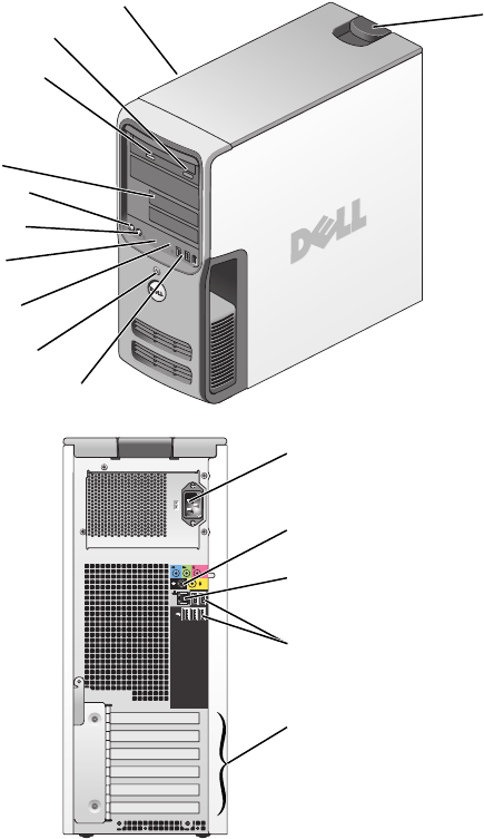
Removing and Installing Parts 65Front View of the Computer1 cover latch release Use this latch to remove the cover. See "Removing the Computer C
66 Removing and Installing Parts5 IEEE 1394 connector (optional)Use the optional IEEE 1394 connector for high-speed data devices such as digital video
Removing and Installing Parts 67Back View of the Computer231541 power connector Insert the power cable.2 sound card connectors (5)• Line-in connector
68 Removing and Installing PartsRemoving the Computer Cover CAUTION: Before you begin any of the procedures in this section, follow the safety instru
Removing and Installing Parts 695Locate the three hinge tabs on the bottom edge of the computer.6Grip the sides of the computer cover and pivot the co
Contents 75 Appendix . . . . . . . . . . . . . . . . . . . . . . . . . . . . . . . . . . 109Specifications . . . . . . . . . . . . . . . . . . . . .
70 Removing and Installing PartsInside View of Your Computer CAUTION: Before you begin any of the procedures in this section, follow the safety instr
Removing and Installing Parts 71System Board Componentsmemory module connectors (1, 2, 3, 4)main power connectorprocessor and heat sink connectorfan c
72 Removing and Installing PartsMemoryYou can increase your computer memory by installing memory modules on the system board.For information on the ty
Removing and Installing Parts 73 NOTE: Memory purchased from Dell is covered under your computer warranty. NOTICE: If you remove your original memory
74 Removing and Installing PartsInstalling Memory CAUTION: Before you begin any of the procedures in this section, follow the safety instructions in
Removing and Installing Parts 755Align the notch on the bottom of the module with the crossbar in the connector. NOTICE: To avoid damage to the memor
76 Removing and Installing Parts NOTICE: To connect a network cable, first plug the cable into the network wall jack and then plug it into the comput
Removing and Installing Parts 77PCI CardsIf you are installing or replacing a card, follow the procedures in the next section. If you are removing but
78 Removing and Installing Parts3Push the two release tabs on the card retention door from the inside to pivot the door open. Because the door is capt
Removing and Installing Parts 79 CAUTION: Some network adapters automatically start the computer when they are connected to a network. To guard again
8 Contents
80 Removing and Installing Parts10Close the card retention door by snapping it into place to secure the card(s). NOTICE: Do not route card cables ove
Removing and Installing Parts 81 NOTE: Installing filler brackets over empty card-slot openings is necessary to maintain FCC certification of the com
82 Removing and Installing PartsInstalling a PCI Express Card1Follow the procedures in "Before You Begin" on page 63.2If present on your com
Removing and Installing Parts 834If your computer includes a card retention mechanism:aPivot the mechanism upward and gently squeeze in on the sides t
84 Removing and Installing Parts7Pull the securing tab, grasp the card by its top corners, and then ease it out of its connector.8Prepare the card for
Removing and Installing Parts 8511Ensure that:• The tops of all cards and filler brackets are flush with the alignment bar.• The notch in the top of t
86 Removing and Installing Parts15If you installed an add-in network adapter and want to disable the integrated network adapter:aEnter system setup se
Removing and Installing Parts 874Push the two release tabs on the card retention door toward each other and pivot the door open. Because the door is c
88 Removing and Installing Parts NOTICE: Ensure that you release the securing tab to unseat the card. If the card is not removed correctly, the syste
Removing and Installing Parts 89Drive Panels CAUTION: Before you begin any of the procedures in this section, follow the safety instructions in the P
Finding Information 9Finding InformationWhat Are You Looking For? Find it Here• Warranty information• Terms and Conditions (U.S. only)• Safety instruc
90 Removing and Installing Parts3Push from the inside and pivot the drive panel to the left to release the panel from its side hinges.4Set the drive p
Removing and Installing Parts 911Slide the tab on the left side of the drive-panel insert under the center drive panel tab.2Rotate the drive-panel ins
92 Removing and Installing PartsDrivesYour computer supports:• Two hard drives (Serial ATA)• Two FlexBay drives (can contain an optional floppy drive
Removing and Installing Parts 93 NOTICE: To avoid damage to the drive, do not set it on a hard surface. Instead, set the drive on a surface, such as
94 Removing and Installing PartsInstalling a Hard Drive1Unpack the replacement hard drive, and prepare it for installation.2Check the documentation fo
Removing and Installing Parts 95 NOTICE: To connect a network cable, first plug the cable in to the network wall jack and then plug the cable in to t
96 Removing and Installing Parts8Check all connectors to be certain that they are properly cabled and firmly seated.9Replace the computer cover (page
Removing and Installing Parts 975Pull the sliding plate to the right and hold in place.6Slide the floppy drive out of the floppy drive bay.power cable
98 Removing and Installing PartsInstalling a Floppy Drive1If you are installing a new floppy drive, remove the shoulder screws from the inside of the
Removing and Installing Parts 99Media Card ReaderFor information on using the Media Card Reader, see "Using a Media Card Reader (Optional)"
More documents for Computers Dell Dimension 9150/XPS 400


Related products and manuals for Computers Dell Dimension 9150/XPS 400
 (44 pages)
(220 pages)
(78 pages)
(116 pages)
(44 pages)
(220 pages)
(78 pages)
(116 pages)
© 2020, manymanuals.com. All rights reserved. | 1.120 s |
 Manymanuals.com
 Manymanuals.de
 Manymanuals.fr
 Manymanuals.it
 Manymanuals.pl
 Manymanuals.cz
 Manymanuals.es
 Manymanuals-pt.com
Comments to this Manuals